|
|
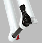
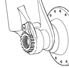
Figure 1: 15mm skewer of QR-15 system
|
For proper and safe adjustment of a QR-15 quick-release, read and follow these instructions carefully.
The QR-15 system uses a 15mm skewer (Figure 1). The skewer passes through the hub. There is a lever, or quick-release lever, on one end of the skewer.
|
|
Figure 1: 15mm skewer of QR-15 system
|
1. With the QR-15 skewer removed from the hub, place the hub ends in the detents (slight indentations) of the fork tips. Make sure all the part are clean. Be careful to center the disc in the disc brake.
2. Pass the QR-15 skewer though the dropouts and hub from the left side of the bike.
3. With the lever in the OPEN position (Figure 2), engage the threads of the QR-15 skewer with the star nut (in the right side of the fork) and gently turn the lever in a circular motion until the skewer is fully threaded into the star nut.
4. Place the lever in the palm of your hand and throw the lever as shown in Figure 3 to the CLOSE position (Figure 5).
At the half-closed position of the lever, there should be some resistance.
5. Test that you have properly adjusted and closed the quick-release.
If the quick-release does not pass any test, follow the adjustment procedures, including the tests, or take your bicycle to your Trek dealer for service.
In the CLOSE position, the QR-15 lever should not interfere with any other bicycle part or accessory part (such as rack or fenders) or touch any part of the bicycle, and should be oriented so obstacles in the path of the bicycle cannot snag the lever (Figures 5).
|
|
Figure 2: Lever positions |
|
|
Figure 3: Swinging motion of quick-release lever |
|
|
Figure 4: Alignment of the front quick-release lever |
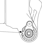
1. Loosen the screw and swing the keeper plate so that it is out of the way (Figure 5).
2. Pull the star nut from the fork tip and rotate. For reference, note the numbers on the star nut and the reference dot of the fork tip (Figure 6).
3. Test that the QR15 passe all wheel-retention tests.
4. Replace the keeper plate and tighten to the torque specifications.
|
|
Figure 5: Keeper plate loosened and rotated to the side |
|
|
Figure 6: Star nut and reference dot |